Station
radio-amateur ON4NB
membre
du GDV, "Gang de Verviers"
QRA-Locator : JO20WN Digimodes, PSK31, SIM 31/63
Contact
:
Utilisation
du CAT sur Kenwood TS-2000
Comme signalé précédemment, à
l’origine, les commandes CAT étaient prévues pour
transmettre les signaux digitaux de type RTTY ( FSK ), packet radio
etc.
Kenwood a donc prévu à l’arrière du TS2000
un connecteur à 13 broches, identifié ACC2.
Pour cette utilisation digitale, on choisit le TX principal ( main-TX
) par la commande TX0 ; ( code hexa 54.58.30.3B ) puis on passe en
émission par la commande CAT « TX ; » ( code hexa
54.58.3B ) . Pour cette utilisation, il n’est donc pas nécessaire
d’utiliser un port COM ; le signal FSK généré
est manipulé par la broche 2 de ACC2, et il est évident
que les bruits audio qui pourraient être présents sur
l’entrée micro ne peuvent avoir aucune influence sur
la qualité de la transmission.
Lorsqu’il s’agit de signaux audio de type PSK, SSTV etc.
le problème est tout différent ! il faut absolument
éliminer les interférences audibles.
Kenwood, dans son TS-2000 a tenté de limiter ces éventuelles
perturbations audio dues aux bruits ambiants du shack en désactivant
automatiquement l’entrée micro pendant la transmission
de fréquences audibles . Et puisque l’entrée micro
est désactivée, le signal audio est transmis via la
broche 11 de ACC2 lorsqu’on active le PTT par la broche 9 de
ACC2.
( Voir schéma illustrant les détails plus bas ).
ACC2 permet aussi de récupérer le signal audio provenant
du récepteur, via la broche 3 pour le récepteur principal,
( ou par la broche 1 pour le récepteur secondaire ) En résumé, pour les transmissions en
sim_psk, le plus confortable est
d'utiliser le connecteur ACC2.
MAIS il y a quand-même un inconvénient,
vous devrez utiliser la ligne DTR pour commuter le PTT.
En effet, si vous utilisez le mode CAT pour d'autres fonctions, (
choix de puissance, de la fréquence, de la bande, de l'antenne
etc. ), les commandes CAT TX0 ; TX ; ne commutent pas l’entrée
micro sur la broche 11 de ACC2 ! et comme la ligne RTS est utilisée
pour les contrôles de flux du port RS232, seule la ligne DTR
peut servir à la commutation du PTT.
( N'oubliez pas de prévoir une isolation galvanique
entre le PC et le TS2000 ).
- Donc, ACC2 permet
de commuter le PTT par la broche 9 ( le micro est
coupé automatiquement ) ) à
condition de commuter le PTT par la broche 9 ( forcée à
0V ). Remarques :
-N’utilisez que la broche 3 de ACC2 pour obtenir la BF du récepteur
principal pour éviter des perturbations provoquées par
la BF du récepteur auxiliaire.
J’ai essayé de connecter les deux récepteurs sur
un jack stéréo ( broches 1 et 3 ) et de récupérer
uniquement le son d’un récepteur en jouant sur la balance
des canaux L-R , mais ça ne fonctionne pas correctement dans
tous les cas. ( exemple : quand le signal entre par la prise micro,
c’est en mono , donc la balance L-R n’est pas disponible
pour supprimer un canal ).
-Les commandes CAT ont la priorité :
La commande CAT complète
pour enclencher le transceiver MAIN-TX est TX0
; TX ;
Dans le programme sim_psk, cette chaîne de caractères
doit être envoyée au TX
en hexadécimal : 54.58.30.3B.54.58.3B
MAIS ATTENTION cette commande étant à l’origine
prévue pour les modes reconnus par le TS2000 comme la RTTY,
si vous utilisez cette méthode plutôt que la commutation
par le PTT, vous devez injecter le signal audio par le connecteur
micro.
En théorie, vous devrez utiliser deux ports série, l'un
pour les transmettre au TX les commandes CAT, l'autre pour la commutation
PTT par le DTR .
Mais vous pouvez aussi vous fabriquer un câble en Y comme je
l'ai représenté sur le schéma plus bas sur cette
page. Le DTR n’étant pas câblé du coté
du TS2000, il suffit de récupérer le DTR et la masse
pour commander la commutation via votre interface.
Le choix du ou des ports série se fait dans la première
fenêtre de configuration, via l’onglet « Setup »,
«Général interfaces setting ».
Pour le TS-2000, si vous utilisez le CAT, il faudra activer deux ports
RS232 exemple : com1 et com2 .
Vous pouvez choisir un port série dans la première fenêtre
et cocher DTR,
Puis utiliser un deuxième port RS232 pour les commandes CAT
Mais, vous pouvez aussi, comme moi, vous fabriquer un câble
avec une dérivation du DTR vers votre interface, et vous pourrez
ainsi utiliser un seul et même port série dans les deux
fenêtres.
Je vous rappelle que si le signal DTR n'est pas utilisé par
le TS2000, le RTS par contre, est câblé jusqu'au transceiver
puisqu'il sert au contrôle de flux !
Donc, injectez plutôt la BF sur la prise micro de ACC2 par la
broche 11, en tenant compte des remarques déjà expliquées
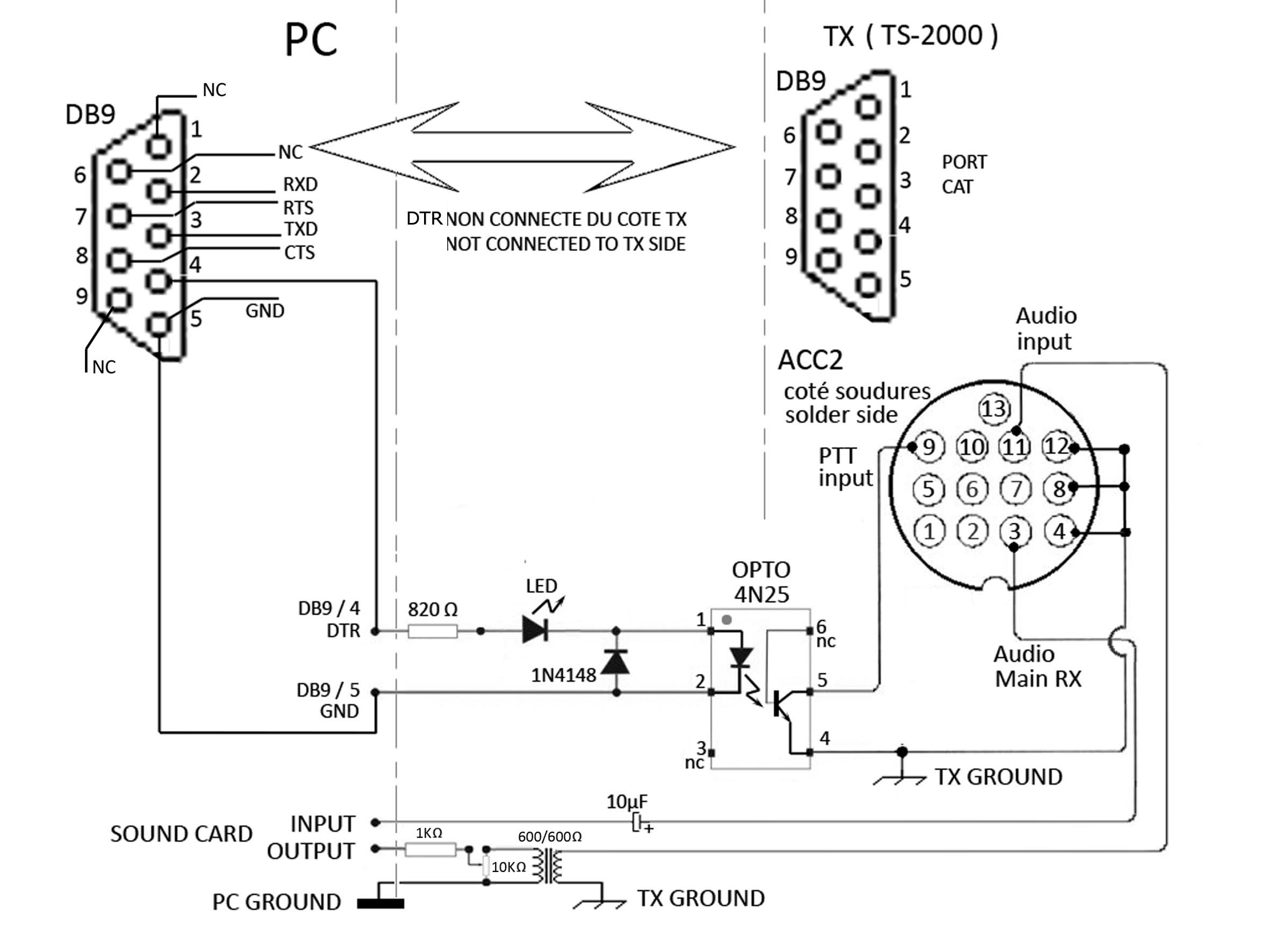
plus haut... Le câble série nécessaire
entre le PC et le transceiver n'est
pas un câble "nul-modem"
c'est un câble droit ; les fils sont
câblés sans aucun croisement ; Il faut au minimum 5 fils
+ la faradisation, et éventuellement le DTR si vous n’utilisez
qu’un seul câble avec une dérivation.
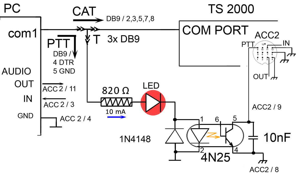
Le schéma est donc tout simple,
deux connecteurs DB9 femelles comme ci-dessous.
Sur le port COM du TS-2000, la ligne
DTR ( broche 4 ) n’est pas câblée, il suffisait
donc que Nizar permette dans son programme sim_psk, d’ activer
ce signal DTR pendant la transmission, pour commuter le PTT via l'interface.
Cette fonction a été implémentée à
partir de la version 5386.
Pour permettre d’utiliser les mêmes fonctionnalités
avec d’autres marques de transceivers, Nizar a séparé
les commandes CAT et rendu accessibles les signaux RTS / DTR en deux
fenêtres distinctes.
Voir plus bas, l’interface que
j’ai bricolée en vitesse pour tester cette fonction.
J’ai
utilisé un opto-coupleur pour isoler galvaniquement les signaux
PC/TX, mais si vous regardez attentivement le manuel fourni avec le
TS-2000, vous constaterez que le PC et le transceiver sont reliés
par un simple câble droit ( pas de croisements ). Donc les masses
et la tresse de faradisation sont en liaison directe, et on peut en
conclure que l’entrée DB9 est déjà opto-couplée.
Par conséquent, on peut supposer que les mêmes précautions
existent pour la connexion via ACC2…
De toute façon, au prix de l’opto-coupleur j’ai
préféré le prévoir même s'il fait
double emploi…
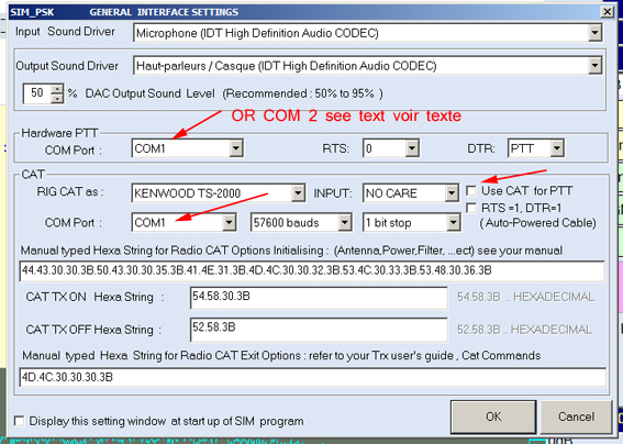
Exemple de configuration du port com
avec câble Y ou de deux ports séparés
******************************************
Using CAT
on Kenwood TS-2000
As explained before,
originally, CAT controls were designed to transmit digital signals
:RTTY (FSK), packet-radio, etc.
So, Kenwood has provided
at the rear of the TS2000 a 13-pin connector, labeled ACC2
Using a digital mode can be made in 2 steps :
first choose the main transceiver, (Hex 54.58.30.3B code) and then,
give the PTT command TX0; (Hex 54.58.3B code)
therefore, for this use
it is not necessary to use a COM port; the generated ( FSK ) signal
is manipulated by pin 2 of ACC2 , and it is obvious that the audio
sounds that might be present on the microphone input can't have any
influence on the transmission quality .
When we want to transmit audio signals PSK or SSTV for example, the
problem is different ; it becomes essential to suppress audible interferences.
Kenwood in the TS-2000 tried to limit such audio disturbances due
to ambient noise from the radioshack, by automatically disabling the
mic when transmitting audible frequencies
And since the mic is disabled, any audio signal must be transmitted
via ACC2 / pin 11, activating PTT when it is switched by the pin 9
of ACC2.
(See the schematic below for more details).
ACC2 also allows to get the audio signal from the receiver via pin
3 of the main receiver, (or from pin 1 of the secondary receiver)
In fact, for sim_psk transmissions, it is most comfortable to use
the ACC2 connector.
But there is anyway a disadvantage : you must use the DTR line to
switch ON the PTT.
You must know that if you use the CAT mode for other functions, such
as the choice of power, frequency, band, antenna, etc. The command
string "TX0; TX;" will switch the transmission ON the air,
but WILL NOT SWITCH the audio onto the mic input ACC2 pin 11 ! therefore
as the RTS line is used by the TS2000 for the RS232 flow control,
only the DTR line is free and can switch the PTT.
(Do not forget to foresee a galvanic isolation between the PC and
TS2000)
- So ACC2 allows to switch ON the PTT, ( the microphone being muted
automatically) as long as you switch ON the PTT by using pin 9 (forced
to 0V).
-Use only the pin 3 of ACC2 to get the BF from main receiver in order
to avoid disturbances caused by the auxiliary receiver.
I tried to connect both the receivers on a stereo jack (pins 1 and
3) and retrieve only the sound of one receiver by altering the balance
of LR channels, but it does not work correctly in all cases. (Eg as
the signal from the microphone jack is mono, so the LR balance is
not available to remove a channel).
-The CAT commands have priority:
The complete CAT command to start the MAIN-TX is "TX0; TX;"
In sim_psk program, this string should be sent to TX in hexadecimal
as follows : 54.58.30.3B.54.58.3B
BE AWARE : this command being scheduled for modes recognized originally
by the TS2000 like RTTY, if you choose this CAT method instead of
switching the PTT , you must inject the audio signal through the microphone
on front panel connector.
In theory, you should use two serial ports, one for transmission of
the CAT commands to TX and the second one for switching the PTT by
DTR.
But you can also make a Y cable as shown hereunder on this page. As
the DTR is not wired on TS2000 side, you just redirect the DTR and
ground to be able to control the switching via your interface.
The choice of one or two serial ports is made in the first configuration
window of sim_psk, via the "Setup" tab, and then "General
interfaces setting".
For the TS-2000, if you use the CAT commands, you'll have to enable
two RS232 ports ex : com1 and com2.
You can choose a serial port in the first window and check the box
DTR,
Then use a second RS232 port for CAT commands ;
But you can also, as I did, make a cable with a derivation of the
DTR from the PC to your interface, and so you can use a same serial
port in both windows.
I remind you that, if the DTR signal is not used by the TS2000, RTS
is wired from the PC to the transceiver because it is used to control
flow!
So rather, you'd better to inject the BF on mic connector ACC2 by
pin 11, taking into account the remarks already explained above ...
The serial cable required
between the PC and the transceiver is
not a "null-modem" cable ! it's a straight cable;
meaning that the wires are soldered without crossing; It requires
a minimum of 5 wires + ground braid to solder at both sides ( and
possibly the DTR to redirect + zero Volt, if you use only one cable
)
The schematic is easy, two DB9 female connectors as below.
On the COM port of the TS-2000, the DTR line (pin 4) is not wired,
thus Nizar who conceived that software, added a possibility to allow
activating the DTR signal from the PC during transmission, to switch
ON the interface via the PTT .
This function was implemented from the 5386 release.
To allow the use the same features with other brands of transceivers,
Nizar did separe the CAT command and made accessible both RTS / DTR
signals from two separate windows.
See below, an interface able to test this feature.
I used an opto-coupler for having a galvanic isolation of signals
PC / TX , but if you look carefully the manual supplied with the TS-2000,
you will find that the PC and the transceiver are connected by a single
straight cable without any particular form of prudence.
So it can be concluded that probably the DB9 inputs are already opto-coupled.
Therefore, we can assume that the same precautions exist for connection
via ACC2 ...
Anyway, the opto-couplers aren't so expensive, so I preferred to use
a few, even if it is duplicated ...